This morning I logged the mains power draw so that I can properly size the fuses.
Mains power here is 240VAC.
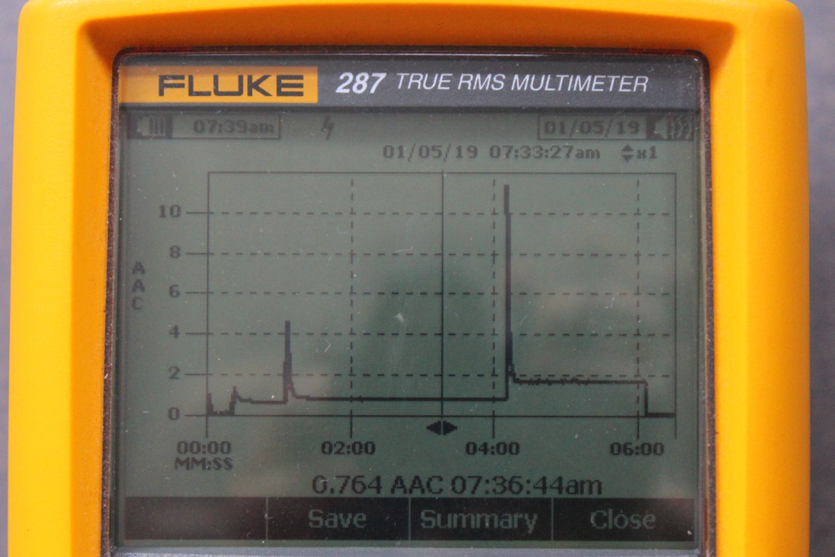
It's a 4 minute startup protocol. It briefly draws an amp when plugged into the wall and the Services LPS fills its capacitors, then settles down to virtually nothing, less than 20w. Then I hit the power foot pedal and the AC filaments/heaters are all lit up and being direct AC there are no caps or other electronics so not much of a spike. The bias and 1st Stages are powered 45 seconds later (just past 1m on the graph) and there is a 5A spike as the power supply caps are filled. That sits at about 150w until three minutes later the DHT, 2nd Stages and Single Stages power supplies are energized. The DMM logs once a second and managed to capture about 11A, which is as much as the mains supply is rated, maybe a little more...perhaps I should put in a soft start. Anyway, after that the amp sits on a pretty neat 400W power draw at idle. Being Class A that should be where it stays even when playing music.
So, 400 watts power draw to light up a combined total of 30w-33w of output power.
|